

|
|
|
|

|

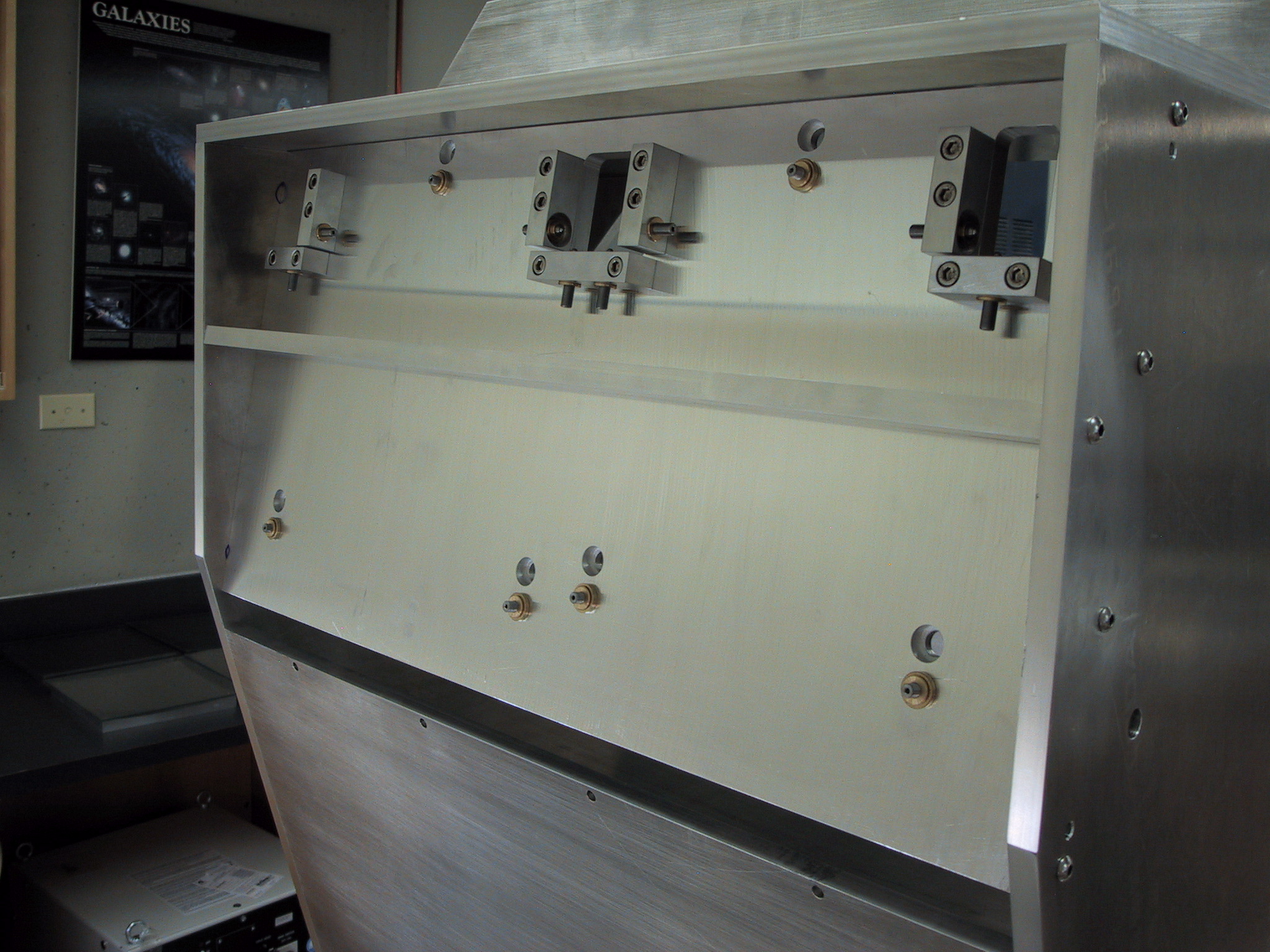
FTS-2 Assembly PicturesPickoff Mirror AssemblyThe pickoff mirror assembly consists of 4 planar diamond-turned aluminum mirrors which intercept two quadrants of the SCUBA-2 beam and feed them through the interferometer. Each mirror is remotely adjustable using 2 piezo actuators, and the whole assembly is moved in and out of the beam on a linear translation stage.
Pickoff Retraction Assemblyunder construction..
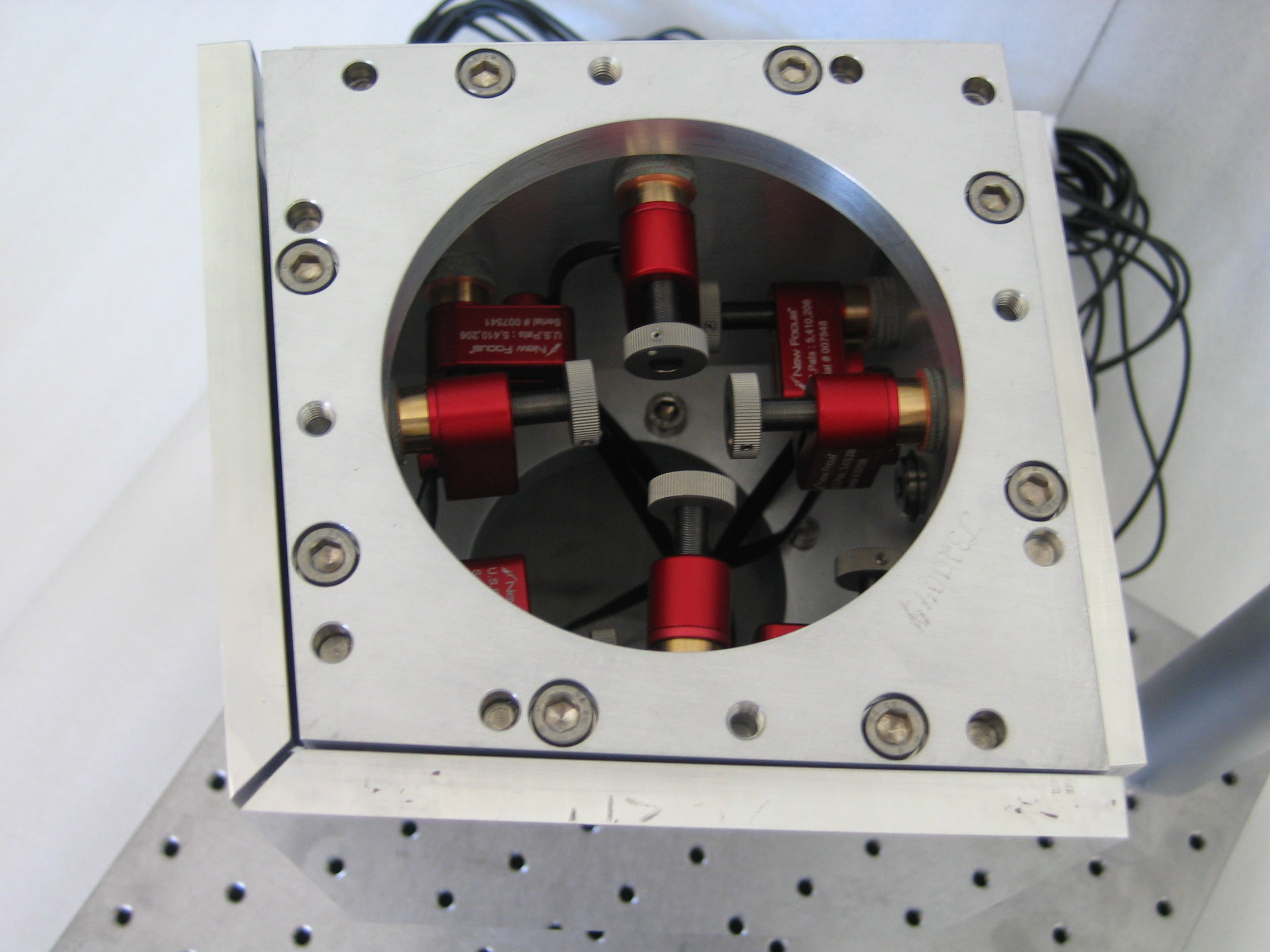
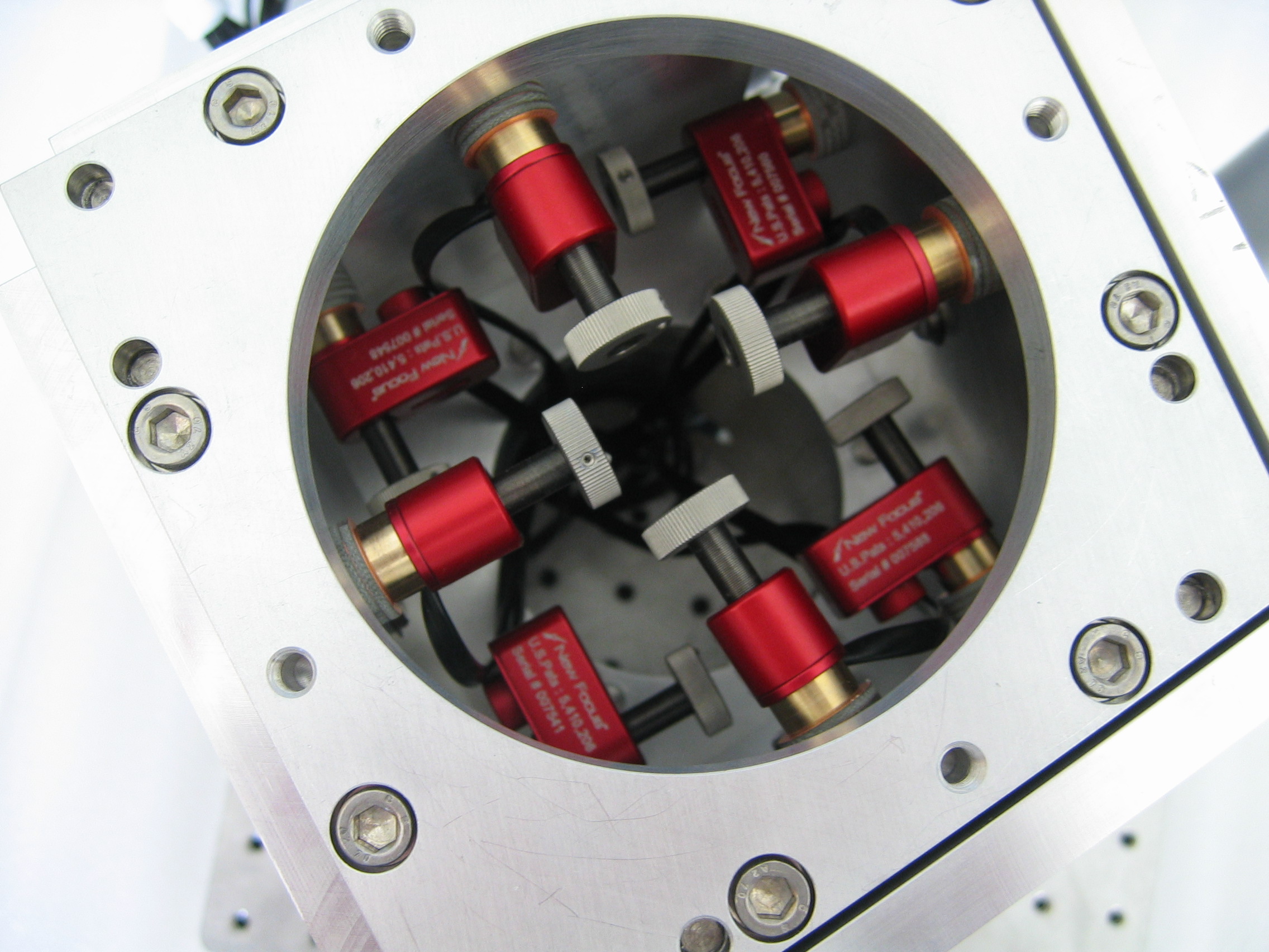
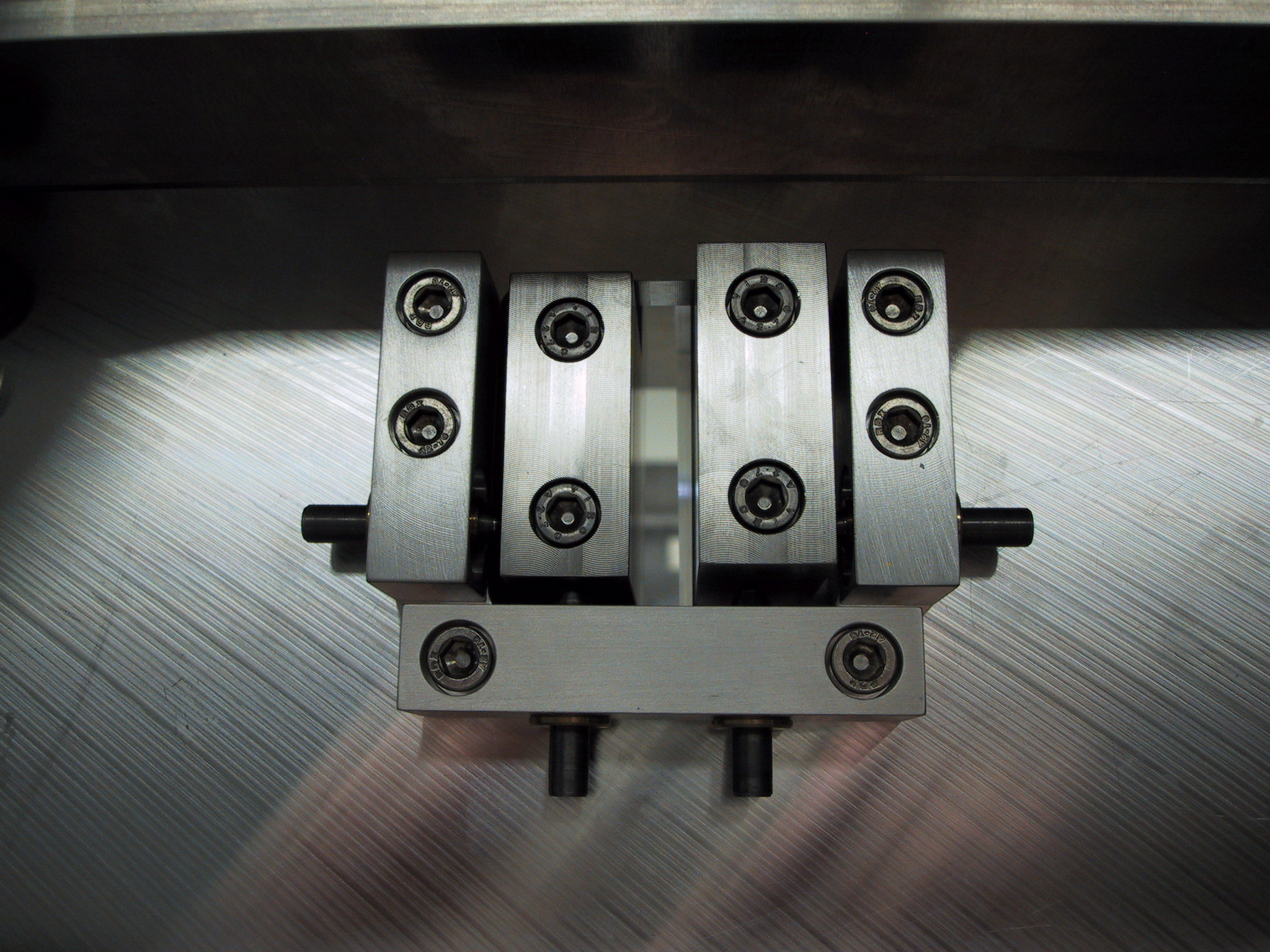
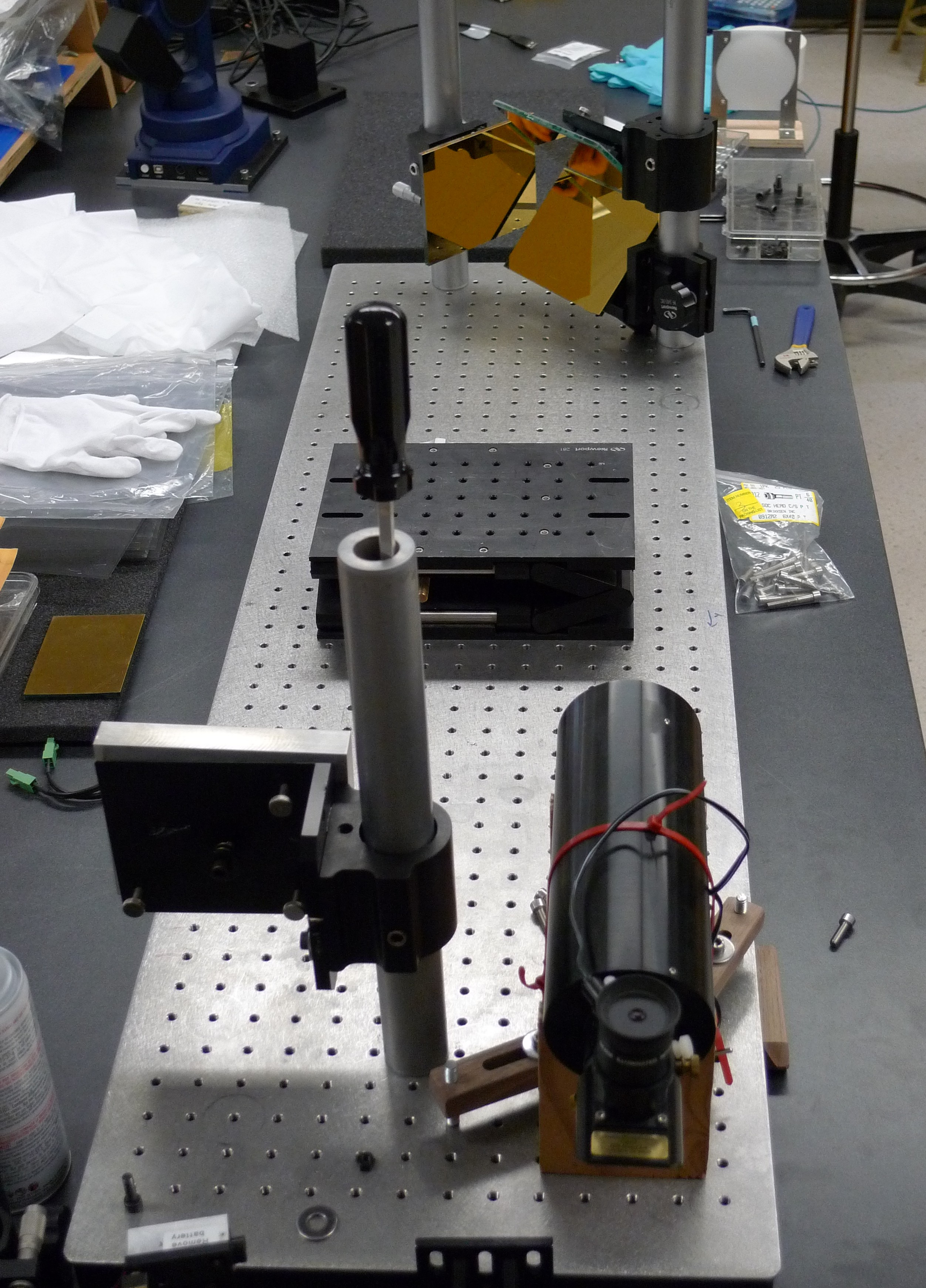
Moving Mirror AssemblyThe moving mirror assembly consists of 2 corner-cube retroreflectors mounted back-to-back on an Aerotech translation stage. Each retroreflector consists of one rooftop mirror block and one plane mirror in order to provide the required shear in the reflected beam while keeping the assembly as short as possible in the vertical dimension. The retroreflector mirror angles are aligned to the order of a few arc-seconds. The two cornercubes can be removed from the translation stage as a unit and replaced without requiring re-alignment, through the use of locating pins on the base plate.
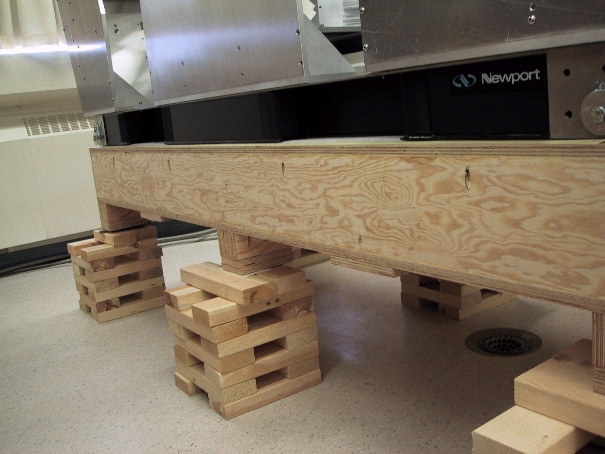
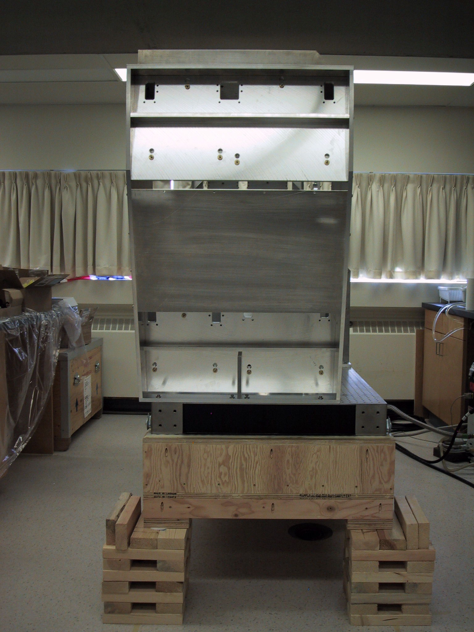
Shipping PlatformThe FTS-2 breadboard will be shipped on a rigid platform, which doubles as the assembly table. At the telescope, the lifting harness must be installed on the breadboard before the rest of the components are installed. The rope eyes shown on the corners are used for lifting the breadboard off of the platform.
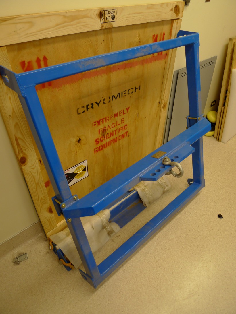
Lifting FrameworkFTS-2 will be hoisted into position using the JCMT overhead crane. A lifting harness was designed to lift the FTS by the corners of the breadboard and provide a means to level the instrument. The framework was built and load tested by a local engineering firm.
Alignment TargetA removable alignment target framework is mounted to the beamsplitter frame which holds the reflective target for the alignment scope. The target is aligned to the rest of the FTS-2 optics using the CMM, so that the target is centered on the ALT axis, and a known distance from the AZ axis. After alignment with the scope, the target framework can be removed without loosing the alignment.
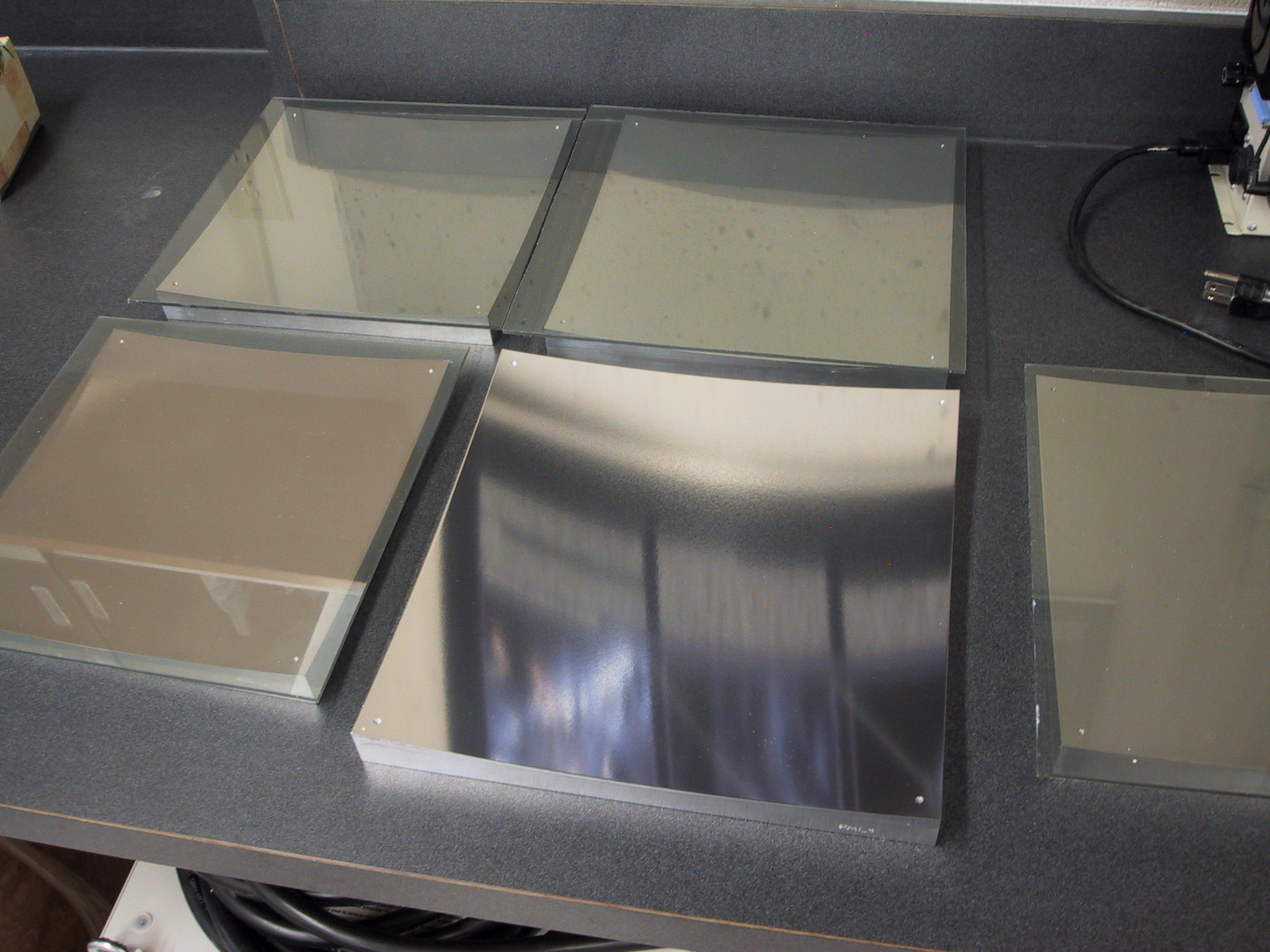
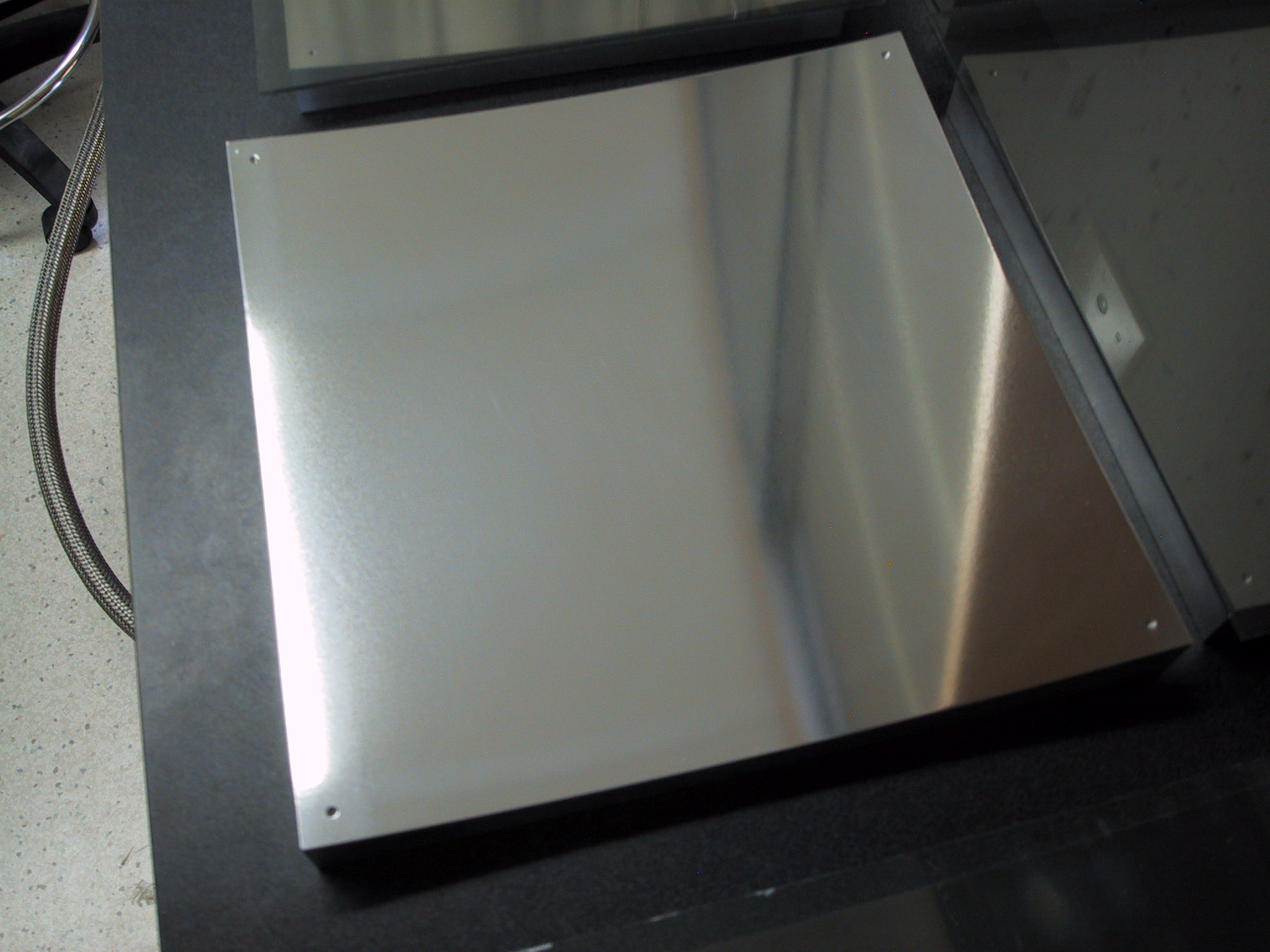
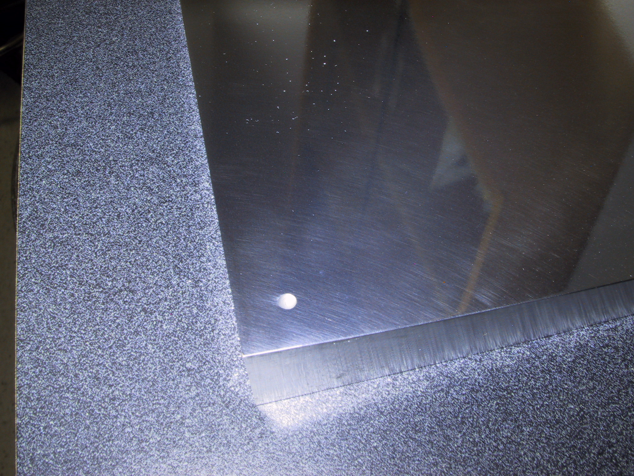
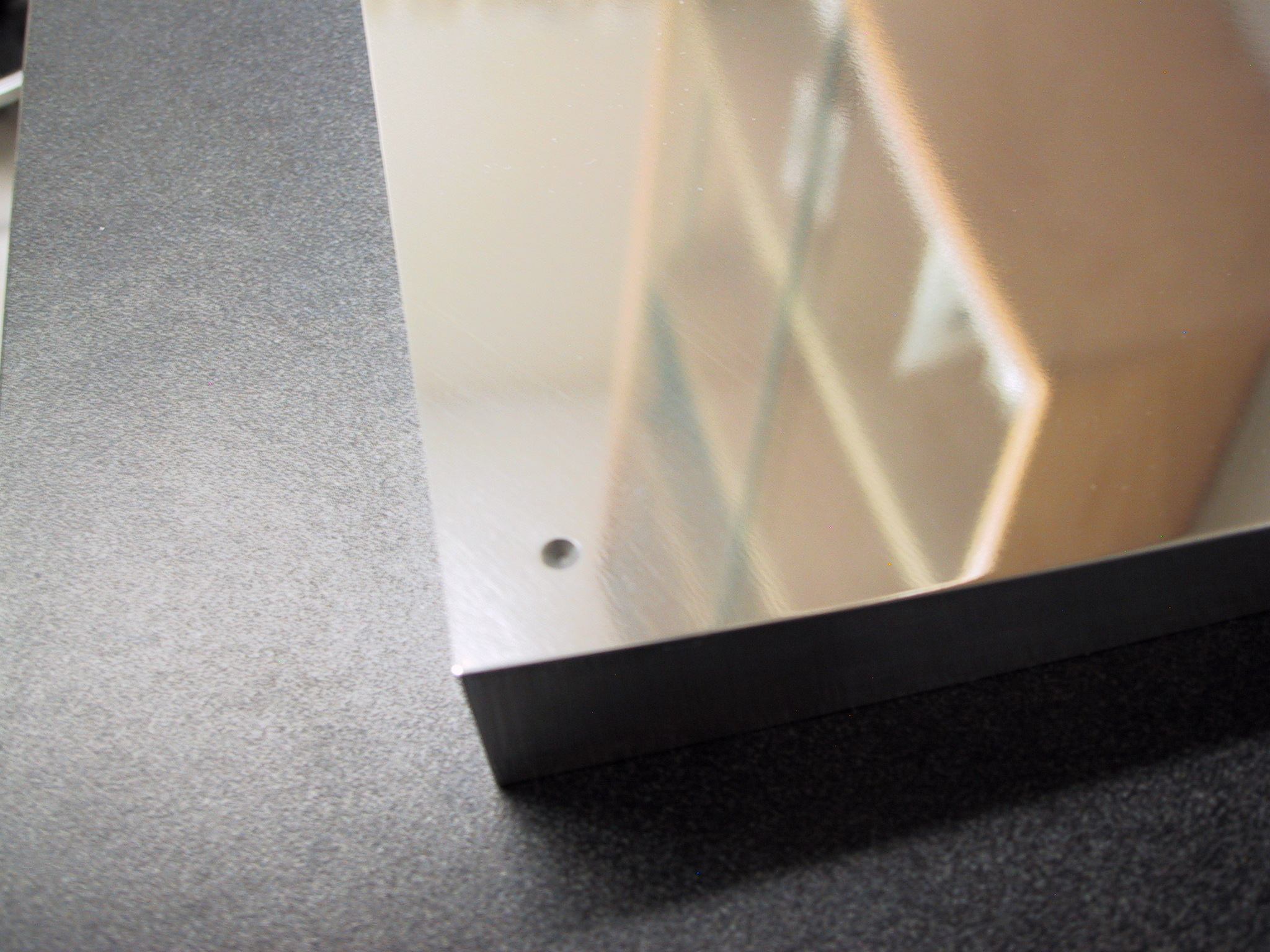
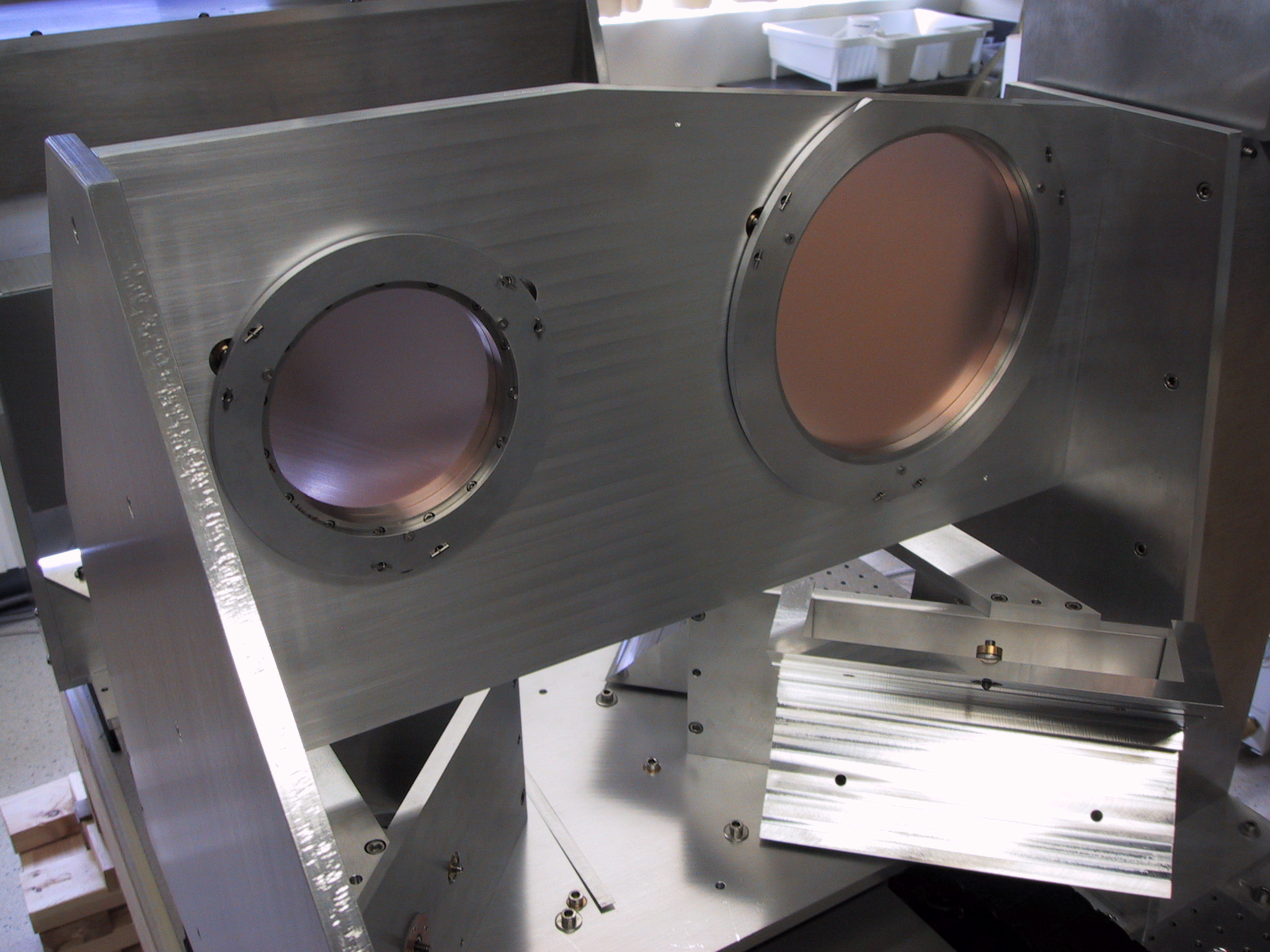
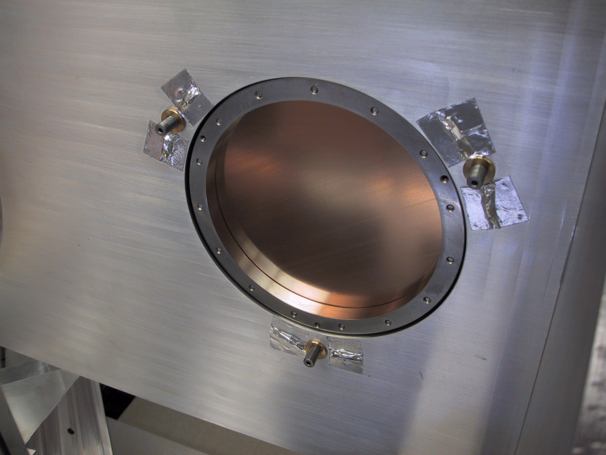
MirrorsAll diamond-turned mirrors have been received from the shop. The surface quality of the flat mirrors is good to optical wavelengths; the aspherical mirrors have a rougher surface but are still fine for submm. Datum divots have been machined into the corners of all the aspherical mirrors to allow mechanical alignment with the CMM.
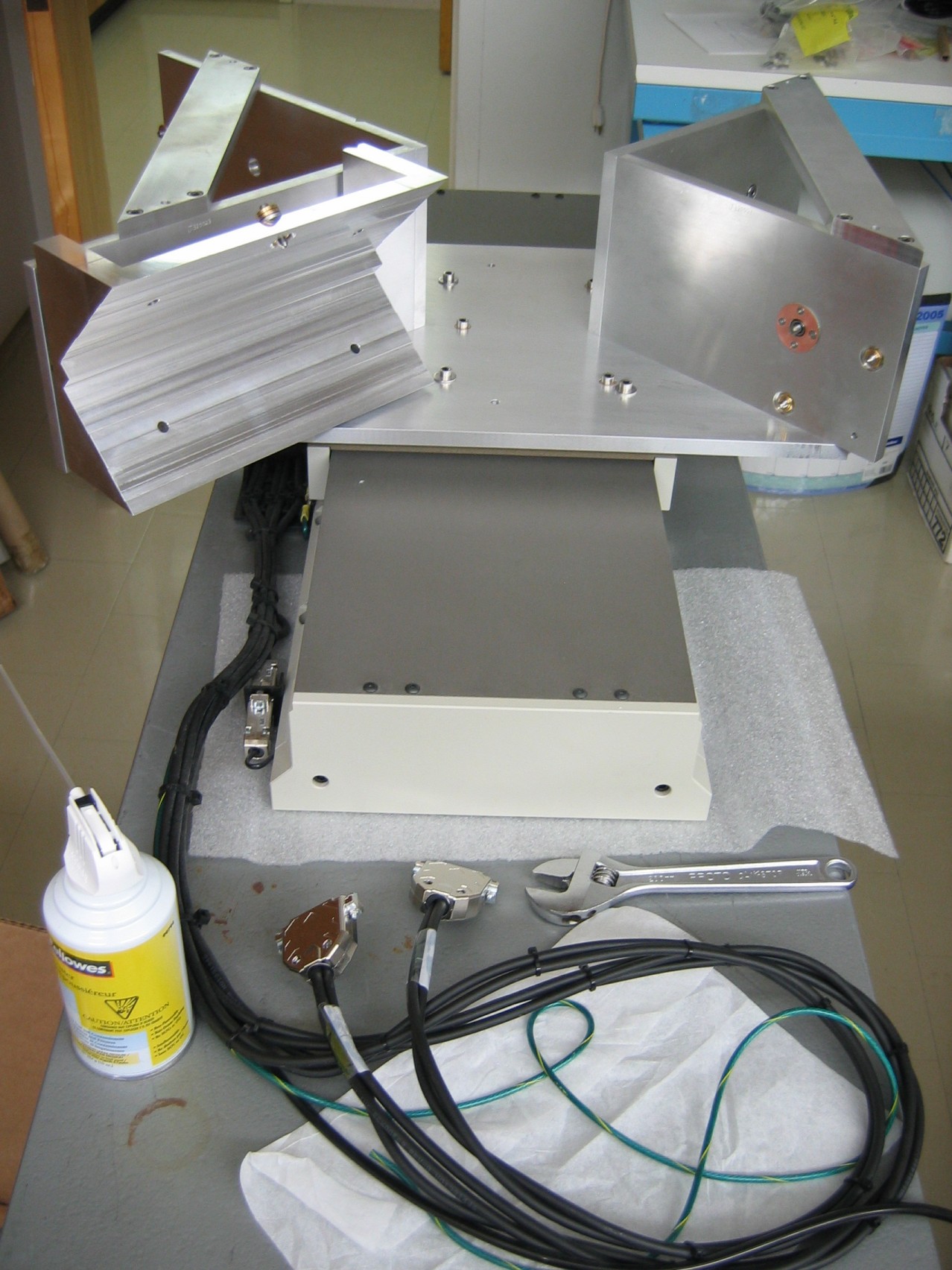
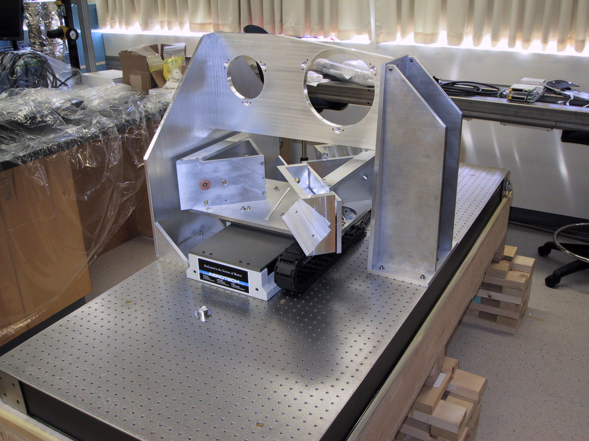
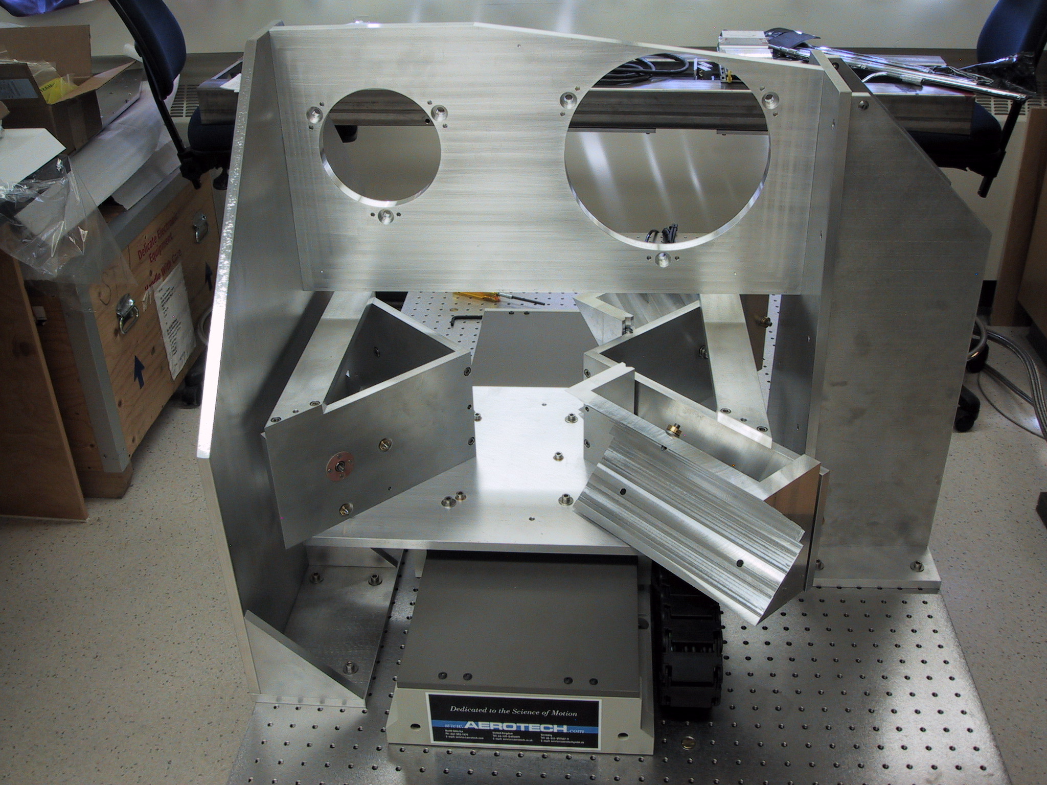
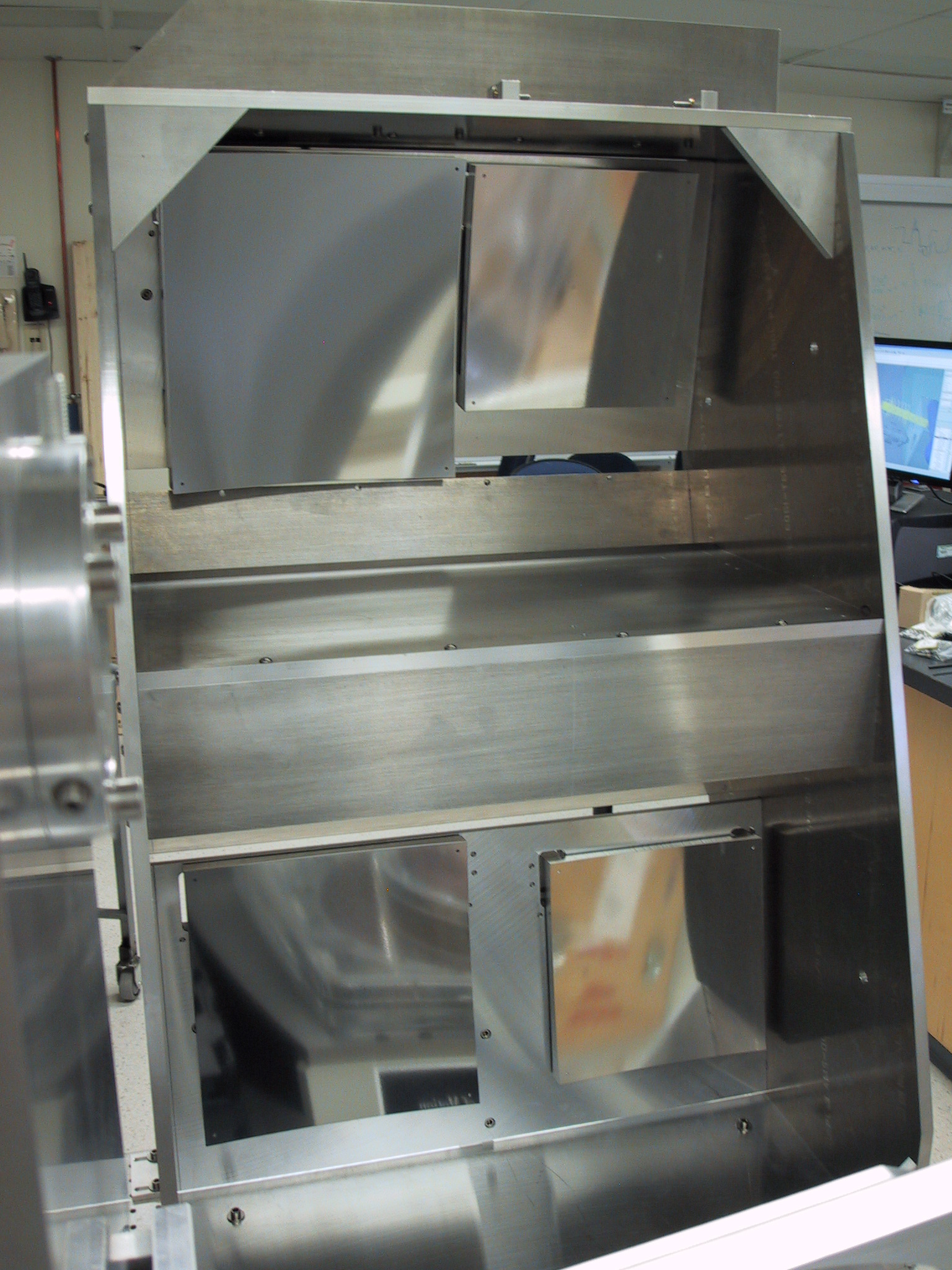
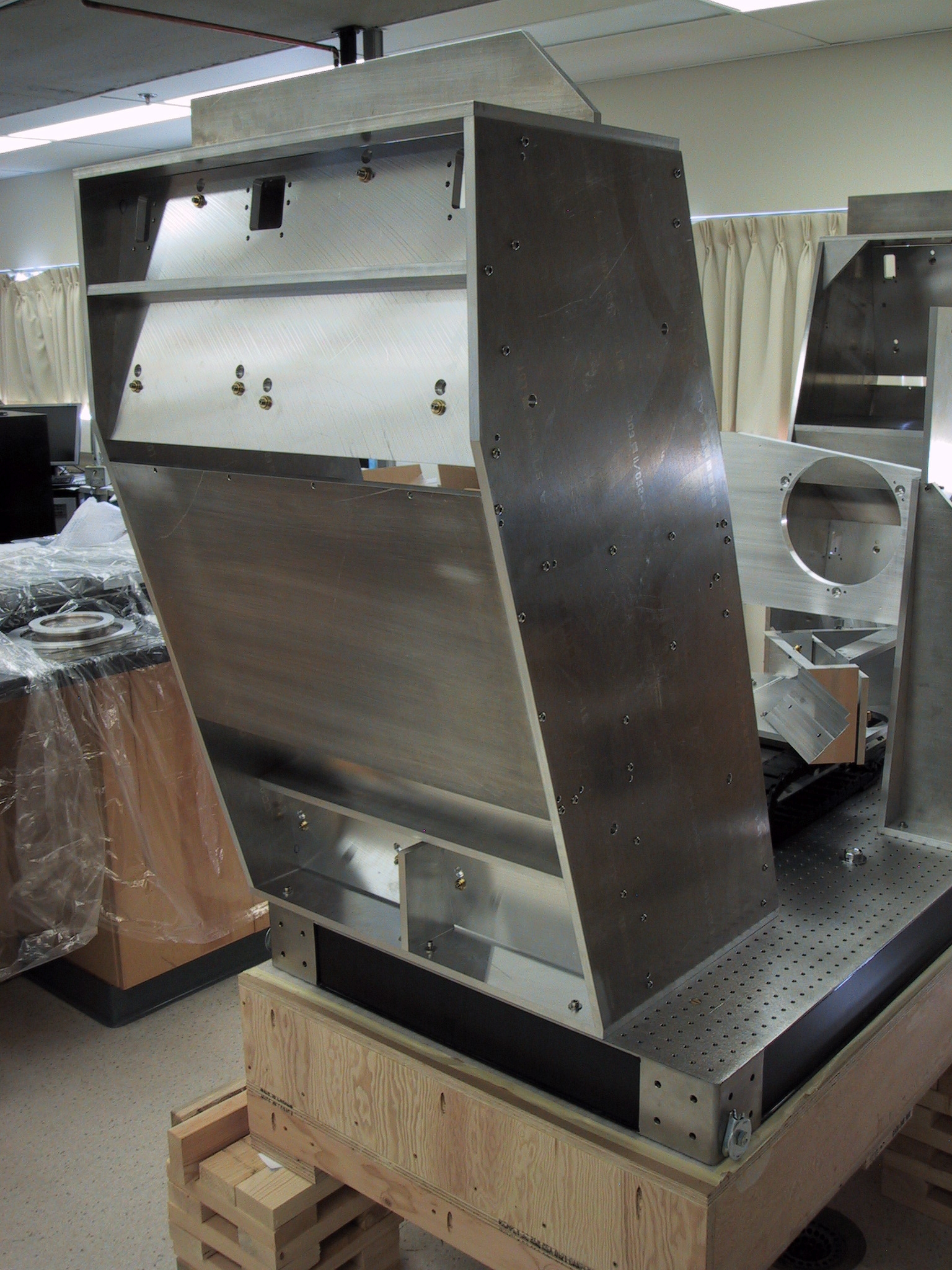
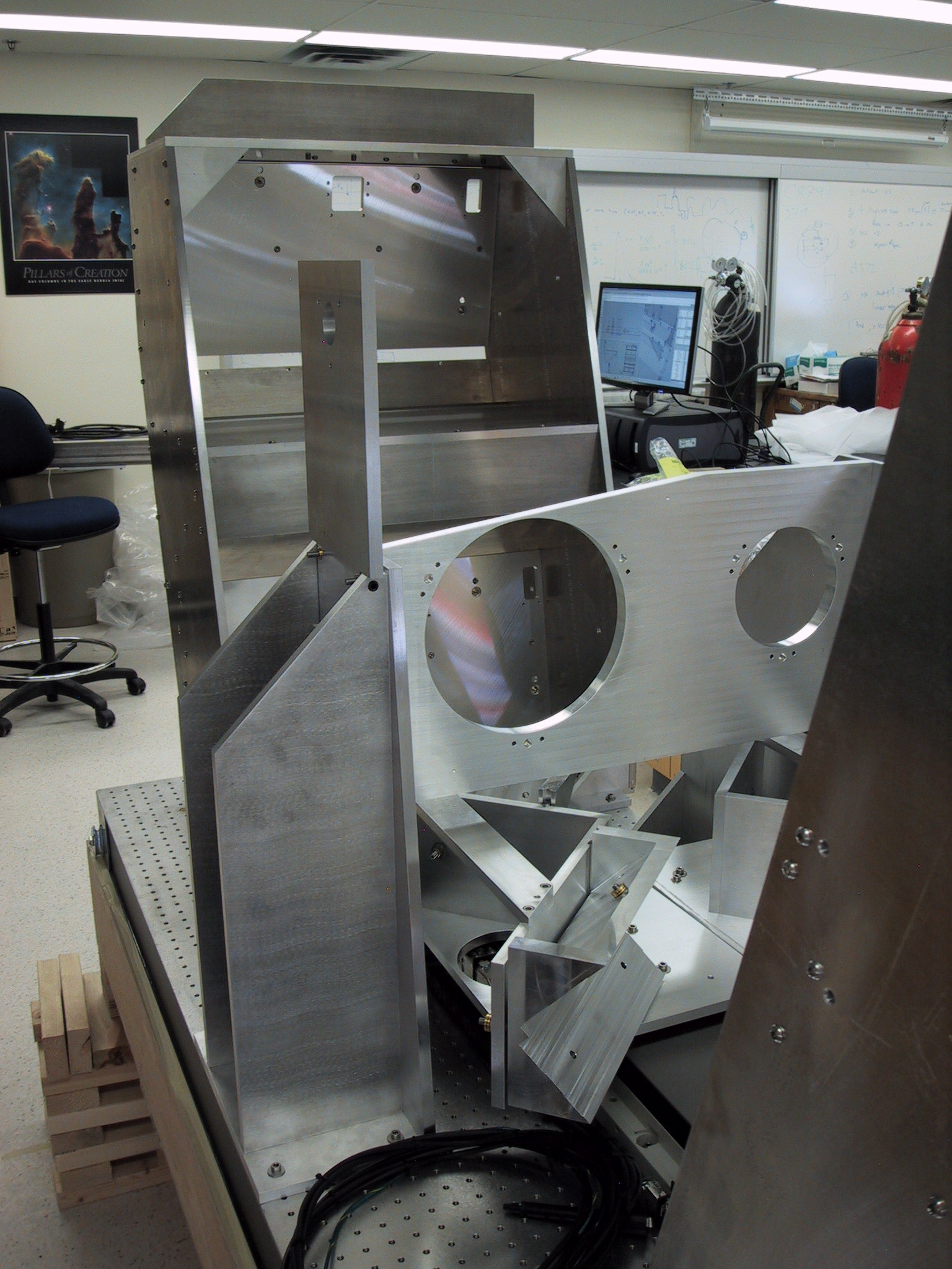
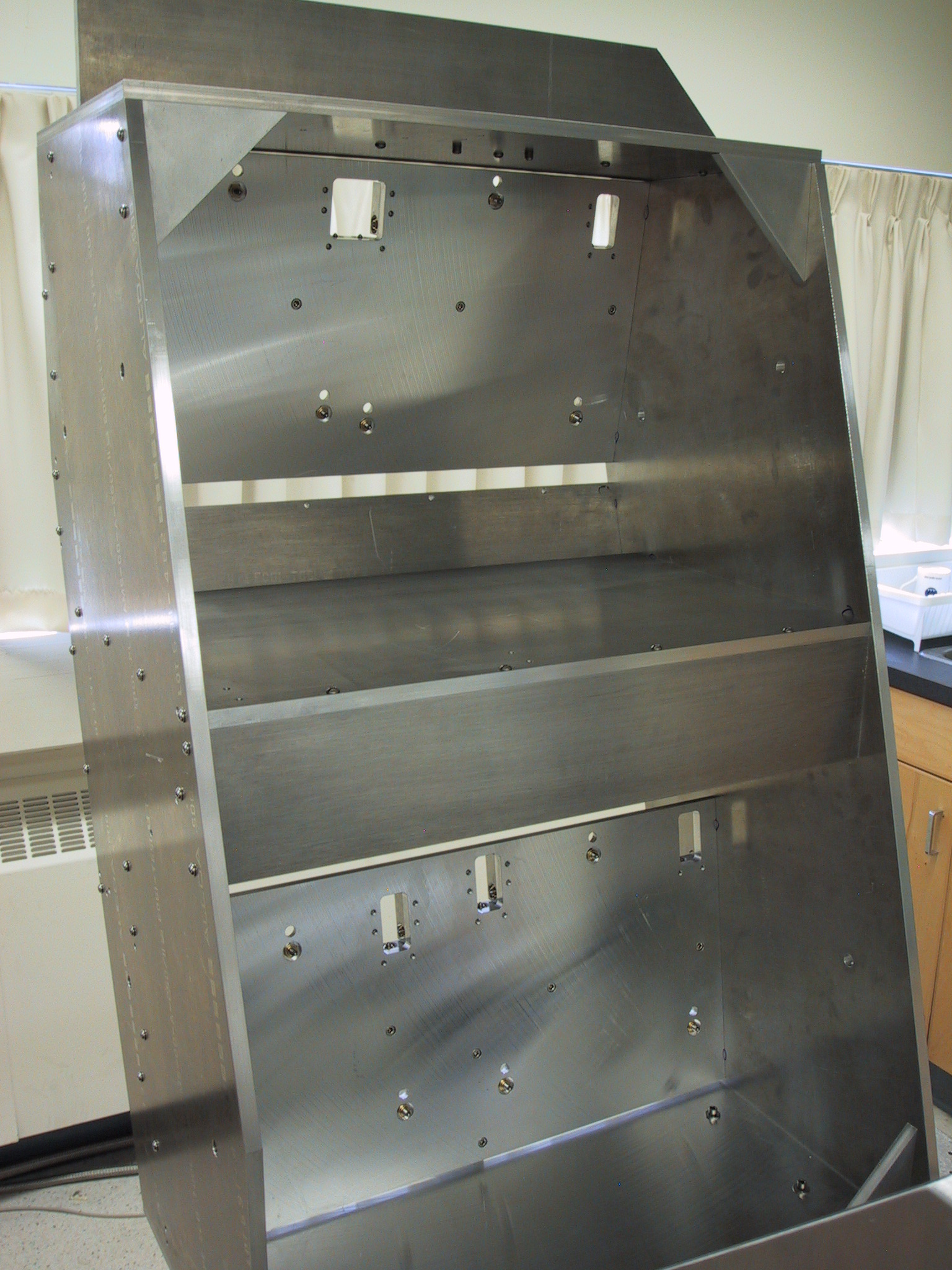
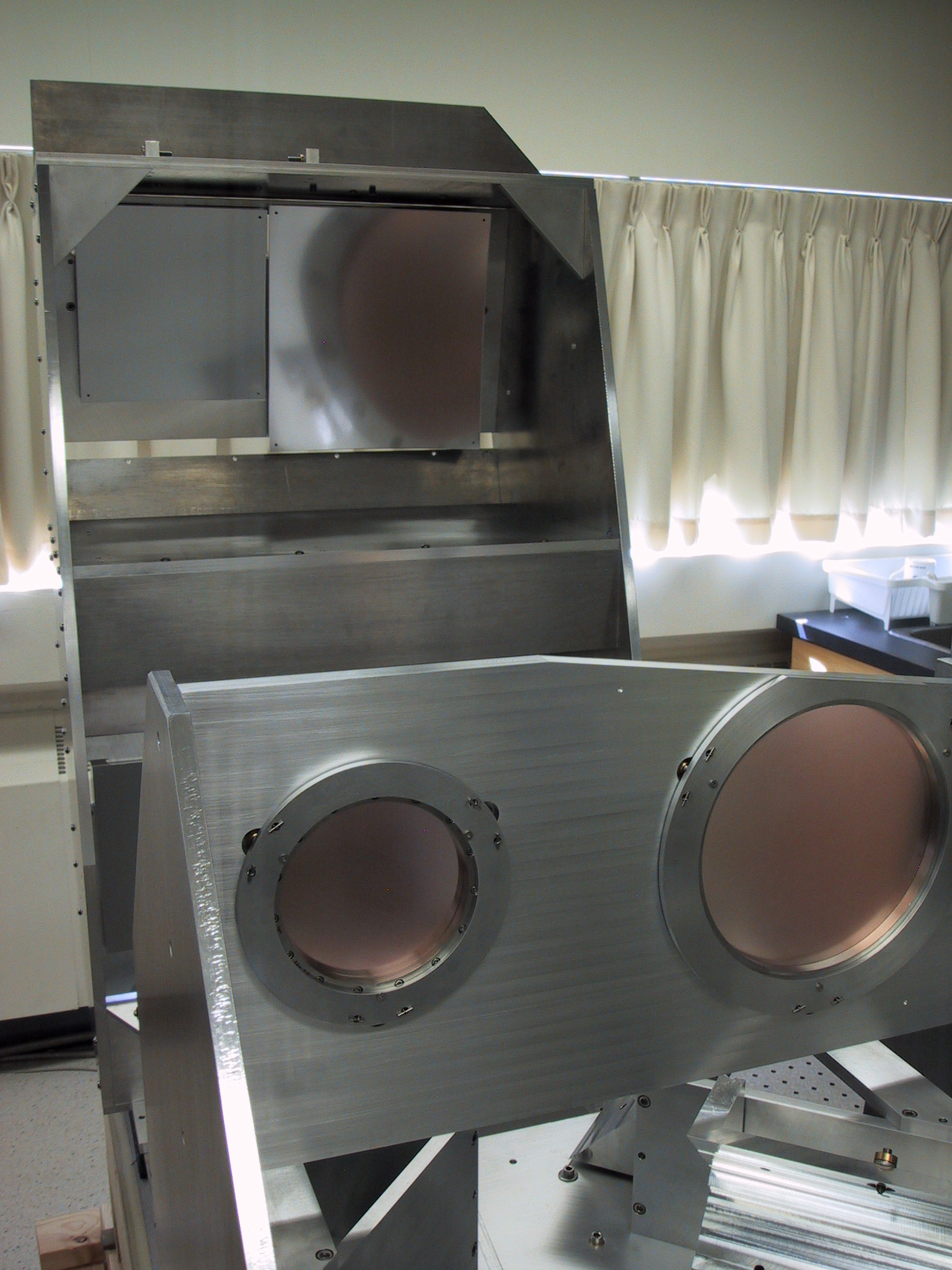
FTS-2 FrameworkThe optics for each side of the interferometer are supported by a 'tower' framework. The optical mounts are integrated into the mirrors and the framework to save space. The towers are aligned to the moving mirror and beamsplitter framework on the breadboard to 0.5mm tolerance; final alignment is achieved using the CMM and the micro adjusters. Locating tabs preserve the alignment of the towers, stage, and beamsplitter unit so that they can be removed for shipping and reinstalled in the same orientation.
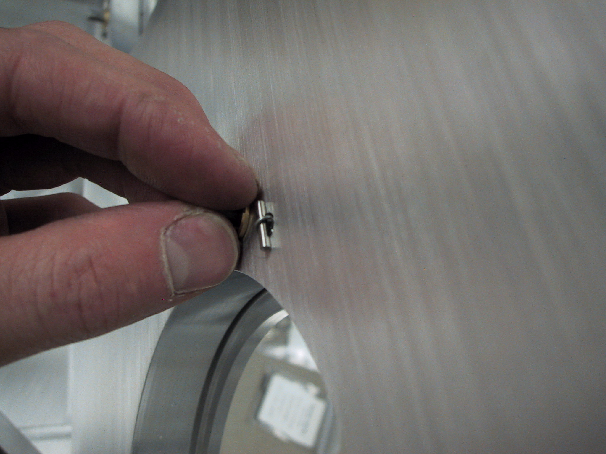
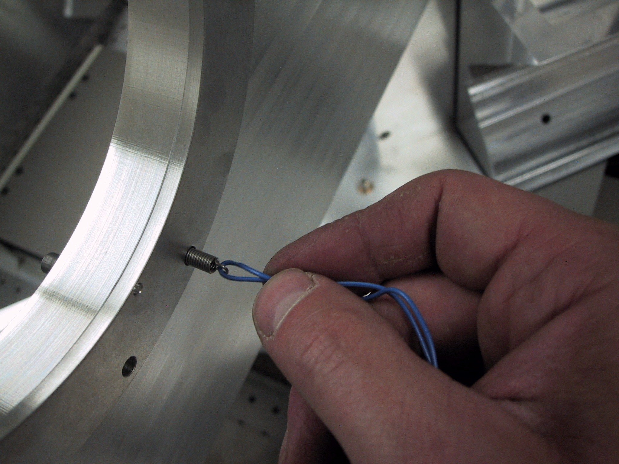
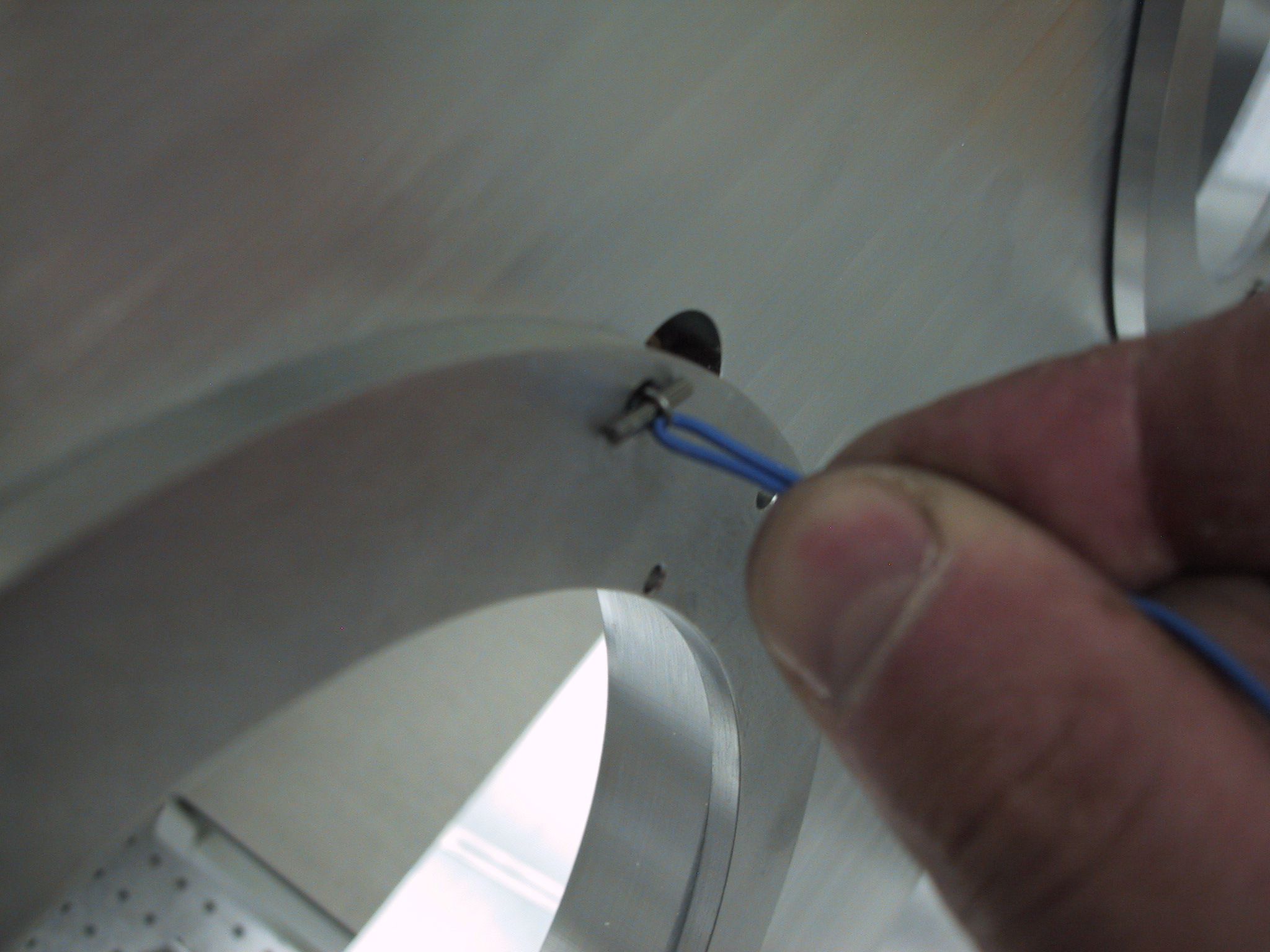
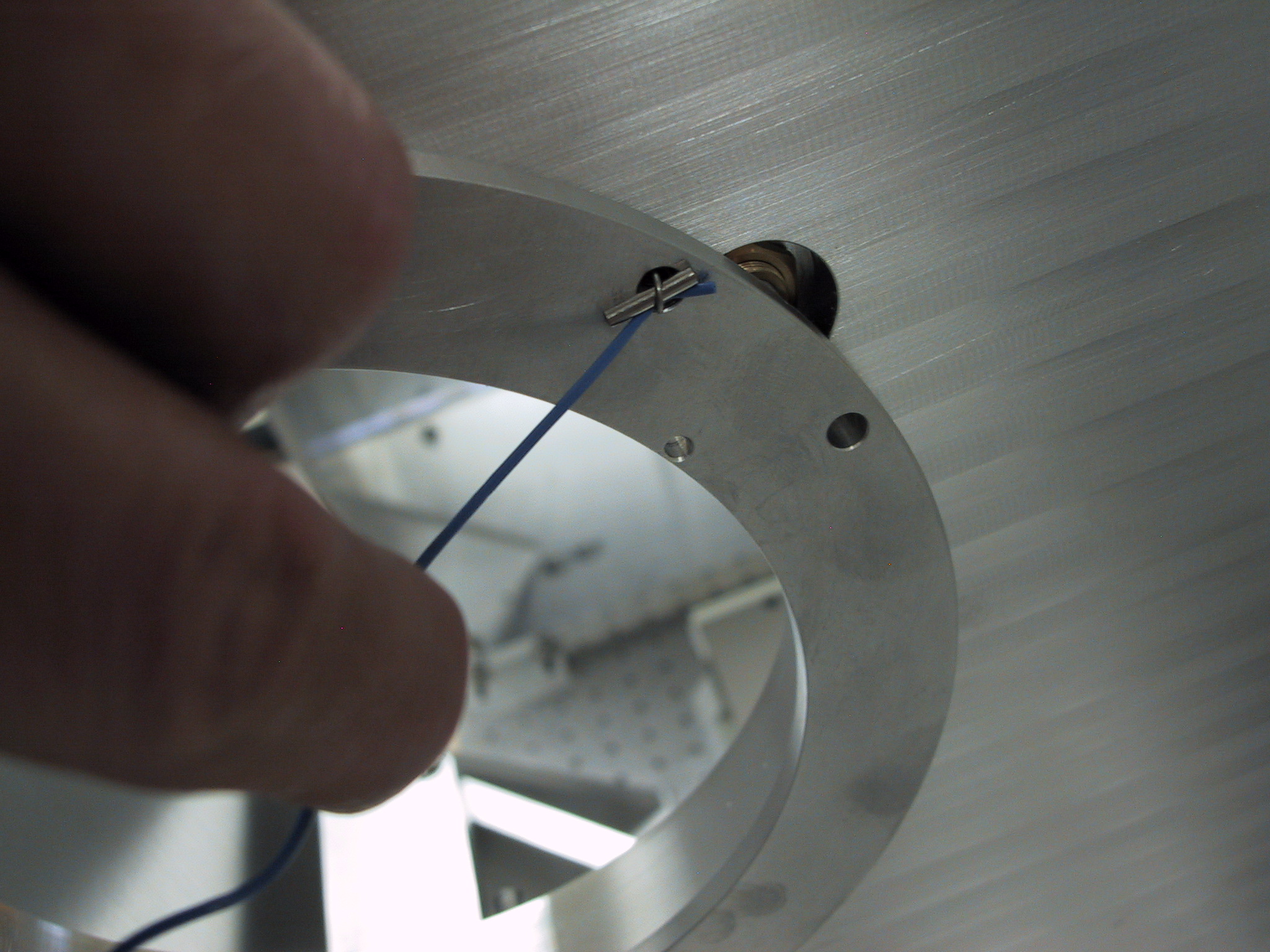
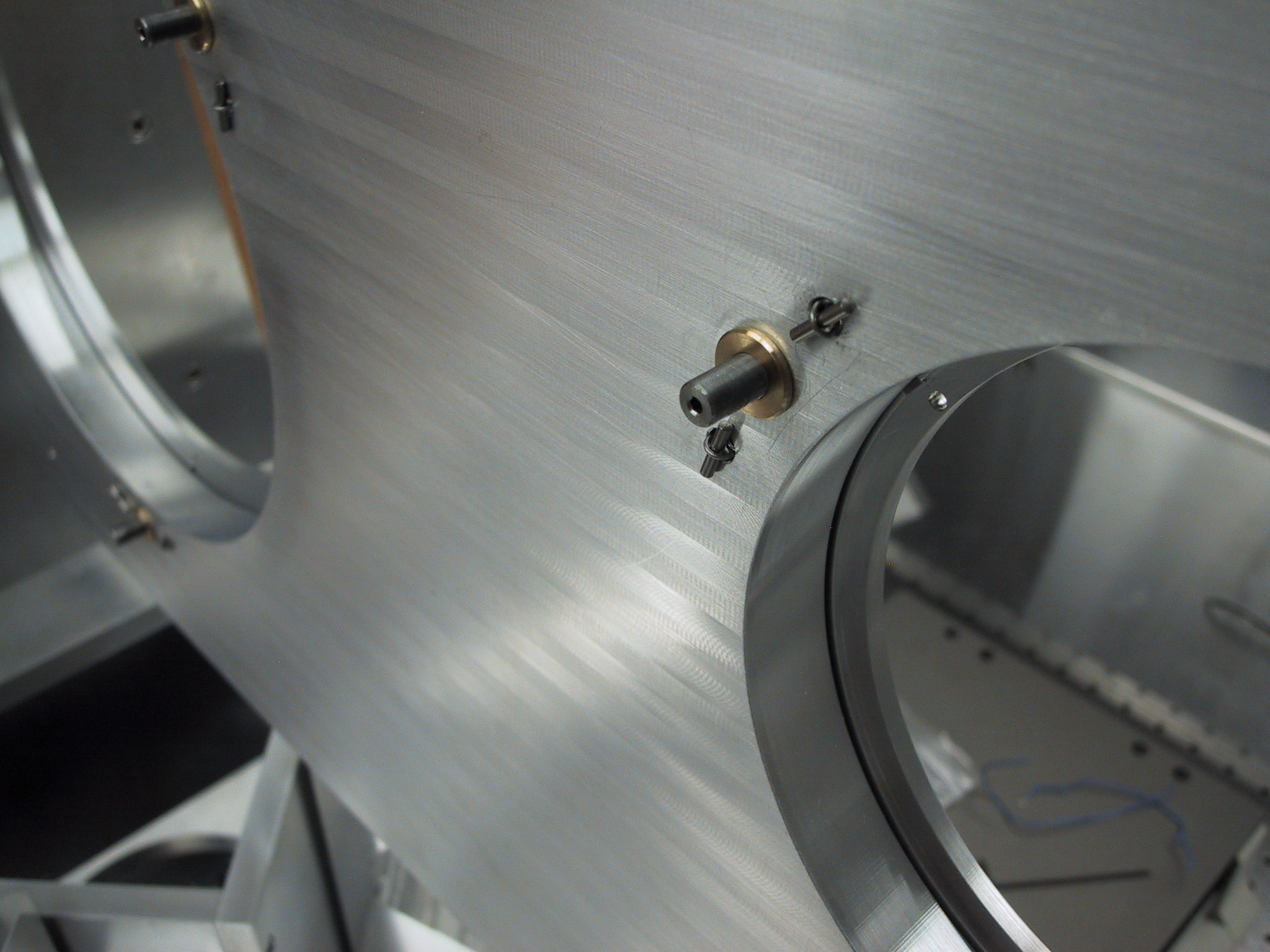
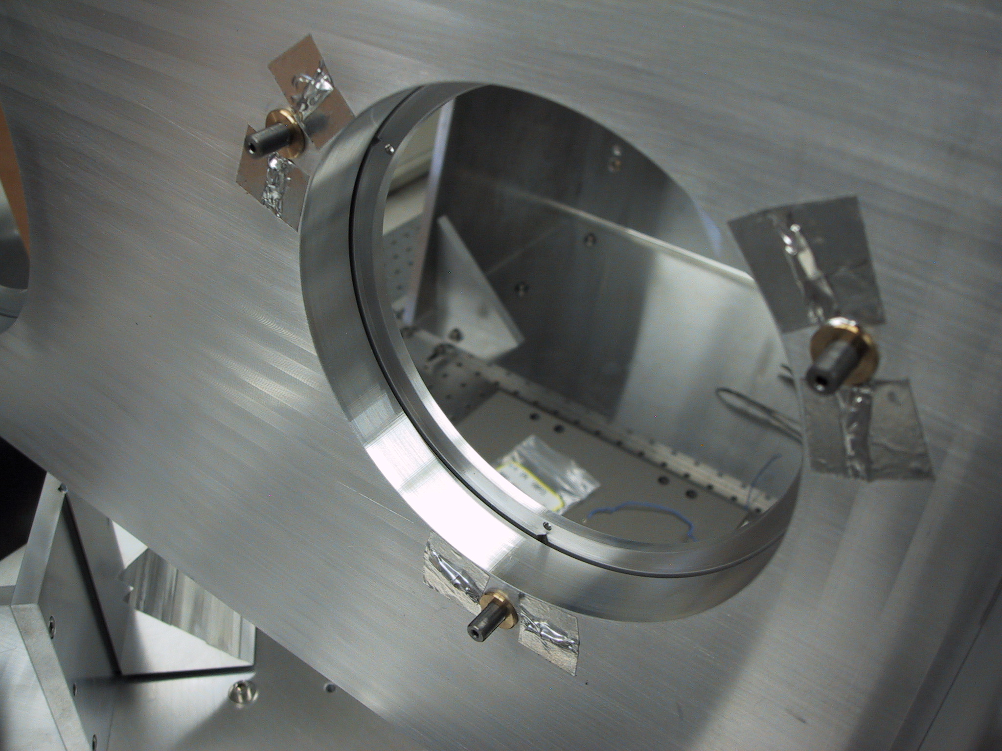
Beamsplitter MountsThe beamsplitters are attached to kinematic mount plates which are held by springs against adjustment screws. The springs are installed by pulling with wire passed through the spring loop, and inserting a 2mm pin. Foil tape holds the springs and pins in place during disassembly.
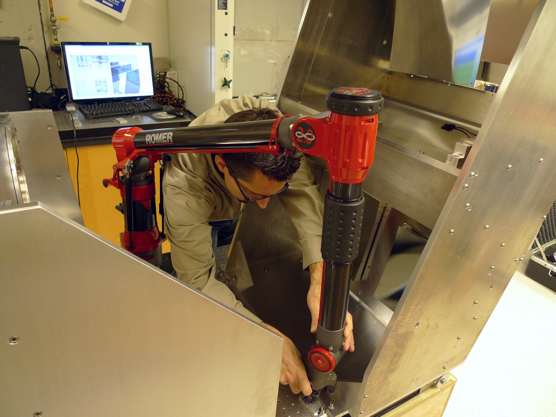
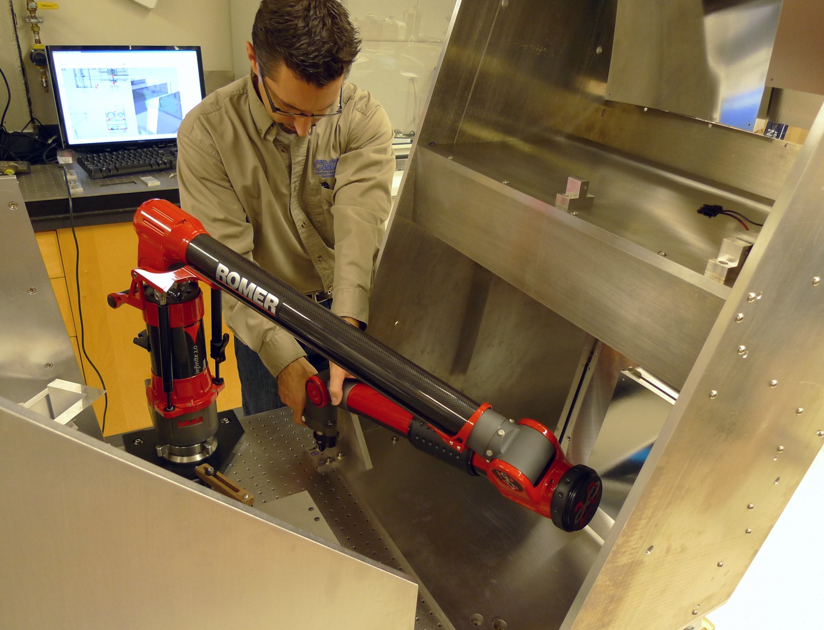
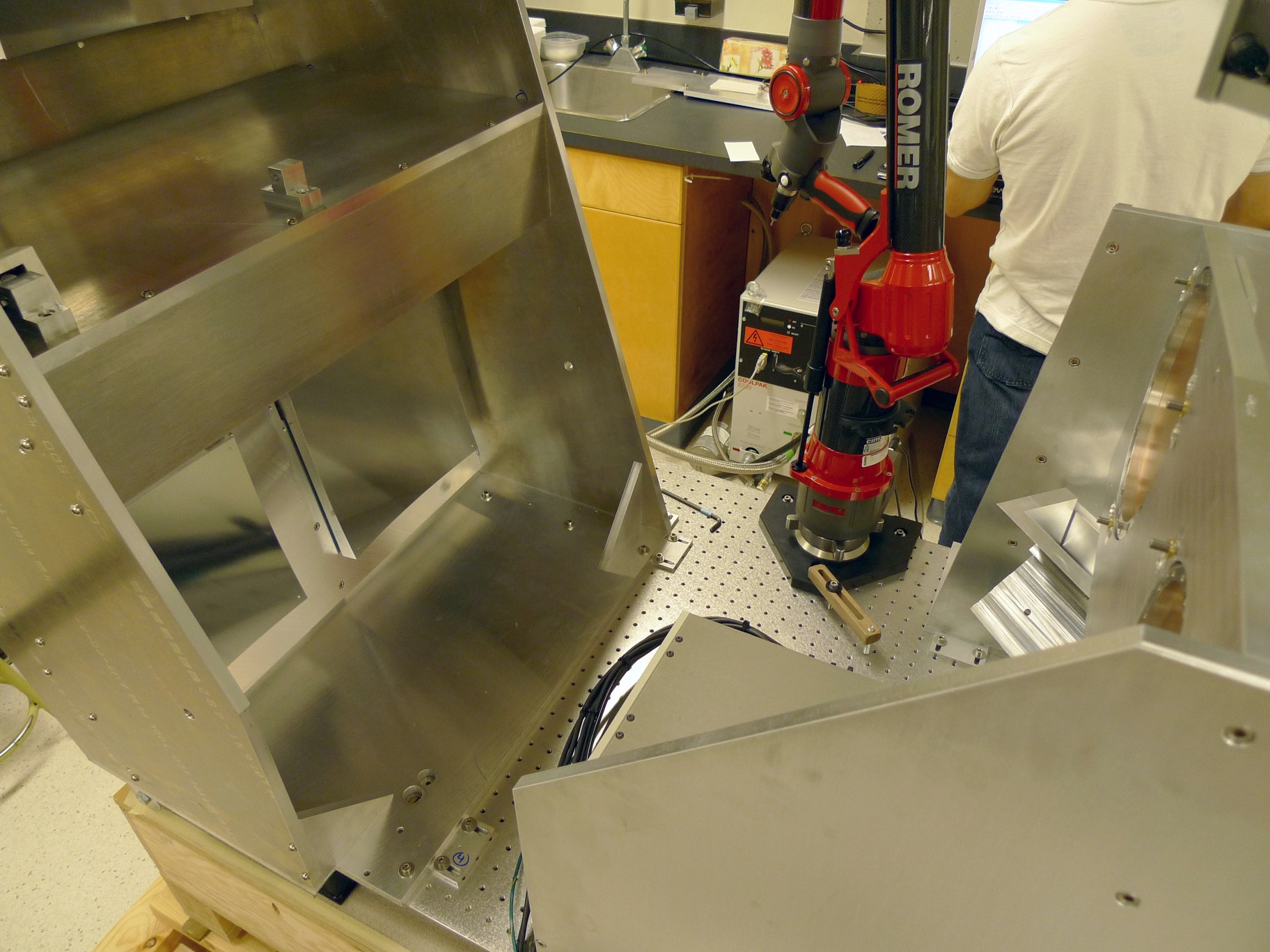
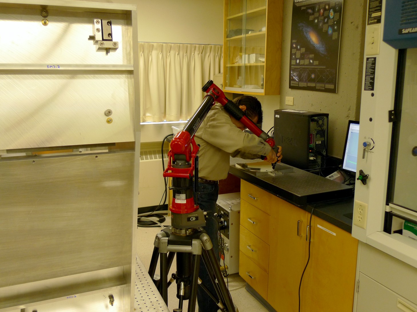
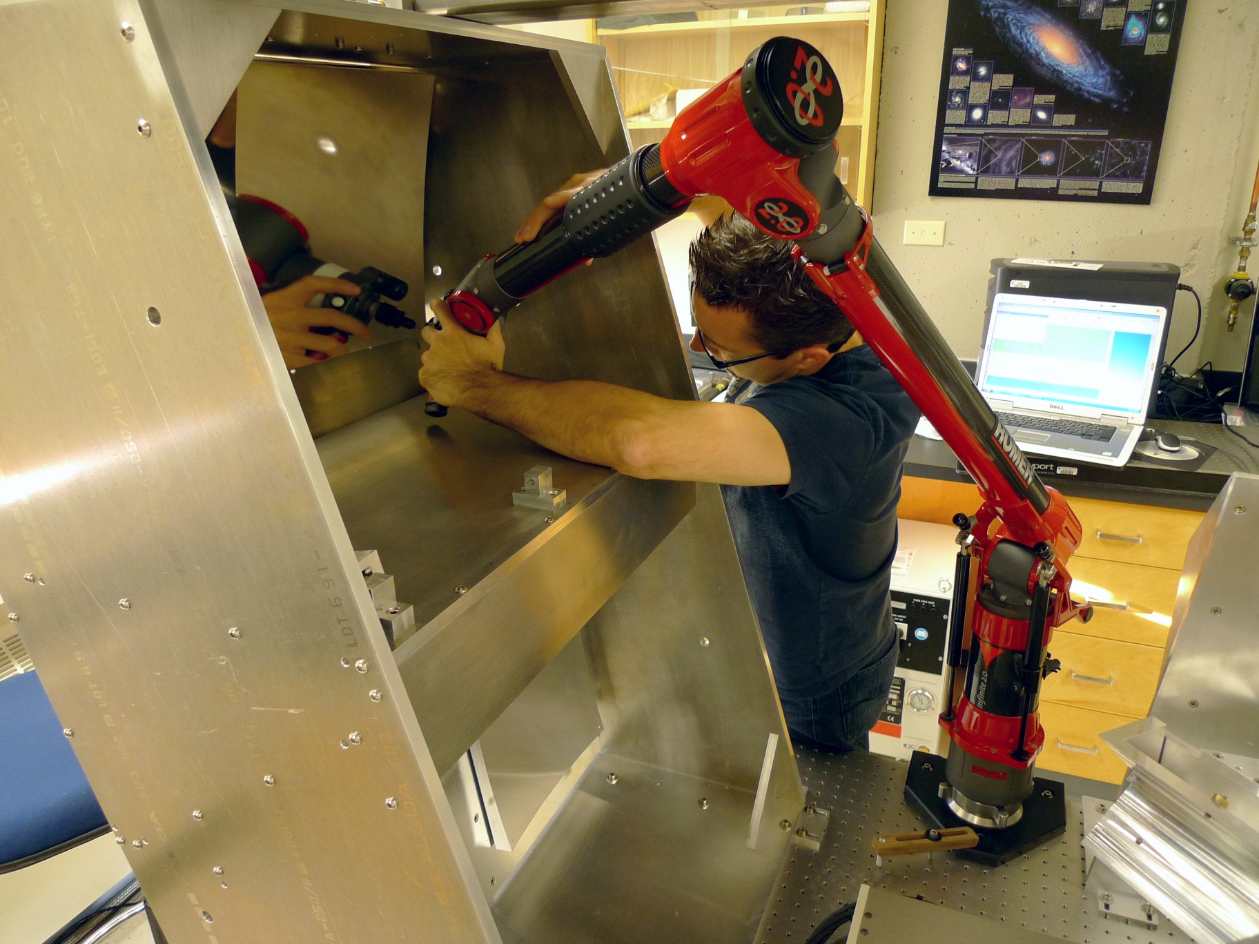
Optics AlignmentDue to the complexity of aligning the aspherical interferometer mirrors using optical techniques, all optics in FTS-2 are aligned using a portable coordinate measuring machine (CMM) to within the tolerance of 0.1mm.
Please send any comments or questions to
|
Last modified on: Monday, 30-Nov-2009 12:00:54 MST