The SPIRE Instrument
The SPIRE instrument has been optimised for its key scientific goals. SPIRE contains a 3-band imaging photometer and an imaging Fourier Transform Spectrometer (FTS), both using bolometric detector arrays cooled to 0.3 K by a 3He refrigerator. The photometer and spectrometer are not designed to operate simultaneously.
The channels will be centred at 250, 350, and 500 µm with a spectral resolution of approximately 3. The field of view is observed simultaneously in all three bands through the use of fixed dichroic beam-splitters. The size of the field of view for the photometer is 4 x 8 arcminutes. This is the largest achievable field of view given the location of the SPIRE field in the HERSCHEL focal plane and the size of the unvignetted field of view for the telescope. Modulation can be provided either by a Beam Steering Mirror (BSM) in the instrument or by drift-scanning the telescope across the sky. The sensitivity of the photometer will be limited by thermal emission from the telescope.

Figure 1: Optical design of the imaging photometer.
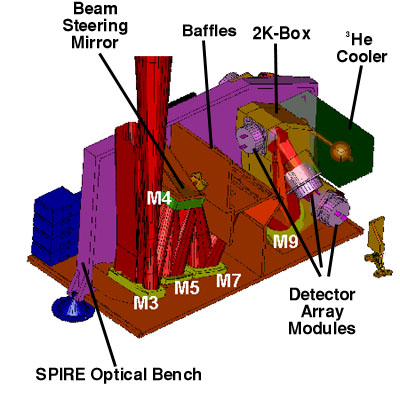
Figure 2: Photometer layout.
The FTS will be of the Mach-Zehnder variety, containing a novel broadband beamsplitter. One of the two input ports will contain a calibration source to effectively null the telescope emission. The two output ports will contain detector arrays covering the ranges 200 - 300 µm and 300 - 670 µm. The mirror travel will be controllable to provide spectral resolutions in the range 20 to 1000. The field of view for the FTS is circular with a diameter of 2.6 arcminutes.
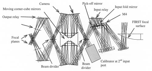
Figure 3: Optical design of the imaging FTS.
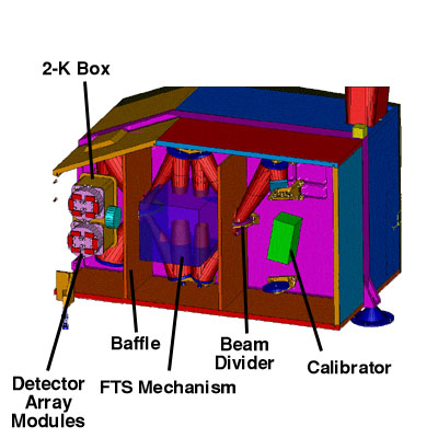
Figure 4: Spectrometer layout.
The SPIRE detector arrays will use spider-web bolometers and NTD germanium thermometers. The bolometers are coupled to the telescope by hexagonally close-packed single-mode conical feedhorns, providing diffraction-limited beams. Each of the arrays is cooled by a thermal strap from the 3He cooler.
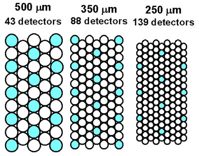
Figure 5: Layout of the photometer arrays. Each array measures 23mm x 45mm. The shaded detectors are those for which there is exact overlap on the sky for the three bands.
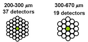
Figure 6: Layout of the spectrometer arrays. The shaded detectors are those for which there is exact overlap on the sky.
